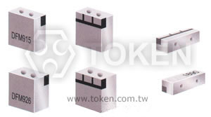
Dielectric Filters (DF-A)
DeMint Offers Dielectric RF Filters for Telecoms. DeMint has extended the capabilities of its filter product line with the introduction of a new range of dielectric microwave filters to the available frequency range up to 5.8GHz. DeMint designs and manufactures custom electronic filters for defence, telecommunications and similar application increasing the range of products available to customers.
Two block-type dielectric RF filters for telecoms basestation applications have been added to DeMint's DF range. The filters have been designed for cellular basestation applications that use a digital pre-distortion amplifier (DPD), as they feature a wide pass band and flat ripple performance, which are required for DPD PA design.
Applications also include RF and microwave communications such as GSM, 3G, GPS, satellite and TV transmission, wireless security systems, radar, CT1, CT2, 900MHz, 1.8GHz, 2.4GHz, 5.8GHz Cordless Phone, wireless earphone, wireless microphone, aerospace and military.
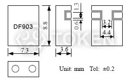
The (DF-A) filter's small size (8.8 x 7.3 x 3.6 mm) means they require more less mounting space compared to DeMint's previous generation of filters for this application. The filters' highly sophisticated multi-pole design ensures high attenuation and good selectivity. Both the two members of the DF series have a ripple of 1.0 dB max.
In addition, DeMint enhances custom design capabilities for specialist applications. Our customers will benefit from the additional frequency ranges now available and from the excellent quality and lower costs achievable
Custom parts are available on request. DeMint will also produce devices outside these specifications to meet specific customer requirements, please contact our sales for more information.
Features :- Suitable for surface mount and reflow soldering.
- Excellent mechanical structure and temperature stability.
- Good selectivity, low insertion loss for using high Q-value resonators.
Download complete PDF Dielectric Filters (DF-A).
| Dimensions (Unit: mm) (DF-A) | |
|
| Typical Specifications (DF-A) | ||||||
| Part No. | Center Frequency (MHz) |
Band Width (MHz) |
Insertion Loss (dB) max. |
Ripple in Band Width (dB) max. |
V.S.W.R max. |
Attenuation (dB) min. (MHz) |
| DF457S30A | 457 | fo±15 | 3.0 | 1.0 | 2.0 | 17 at fo+50; 30 at fo-50 |
| DF522S10A | 522 | fo±5 | 3.0 | 0.5 | 1.6 | 23 at fo+40; 40 at fo-40 |
| DF683S30A | 683 | fo±15 | 2.5 | 1.0 | 2.0 | 20 at fo+64; 30 at fo-64 |
| DF740S30A | 740 | fo±15 | 2.0 | 0.5 | 1.8 | 14 at fo+64; 20 at fo-64 |
| DF864S10A | 864 | fo±5 | 2.5 | 0.5 | 1.5 | 15 at fo+24; 17 at fo-24 |
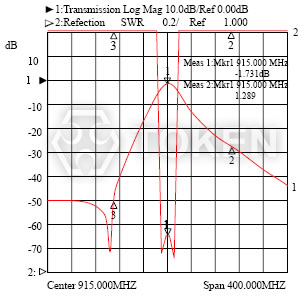
| DF915S25A | 915 | fo±12.5 | 2.0 | 1.0 | 2.0 | 20 at fo+100; 35 at fo-100 |
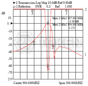
| DF903S6A | 903 | fo±3 | 3.5 | 0.5 | 1.5 | 32 at fo+24 |
| DF927S6A | 927 | fo±3 | 3.5 | 0.5 | 1.5 | 32 at fo-24 |
| DF1890S80A | 1890 | fo±40 | 1.5 | 1.0 | 2.0 | 15 at fo+200; 35 at fo-200 |
| DF2403S20A | 2403 | fo±10 | 3.0 | 0.5 | 1.5 | 35 at fo+75 |
| DF2475S20A | 2475 | fo±10 | 3.0 | 0.5 | 1.5 | 35 at fo-75 |
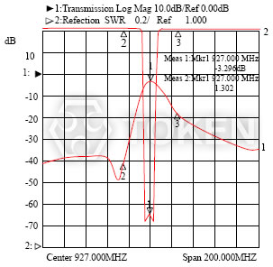
| Typical Characteristic (DF-A) | |
| |
|
|
|
| Order Codes (DF-A) | |||||||||||||||||||||
| DF | 864 | S | 10 | A | |||||||||||||||||
 | | | | | |||||||||||||||||
|
|
|
|
|
|||||||||||||||||