Add To Inquiry Page
Ceramic Filters (LT10.7M)
DeMint (LT10.7M) ceramic filters are compatible with Murata SFELF10M7. DeMint LT10.7M series are monolithic devices which utilize the energy-trapped thickness vibration-mode. This principle of operation is based upon the fact that an excellent resonating element with low spurious vibration can be obtained by adhering to certain theoretical parameters of design. These parameters include the physical dimensions of the peizo element, the electrode pattern, and the associated mass loading effect of the electrodes.
DeMint categorizes the LT 10.7 family according to rank of center frequency. This ranking indicates that a given LT 10.7 will be marked with one of the colors listed in the following chart and will exhibit the center frequency in Technical Characteristics Table.
The (LT10.7M) offers three series: LT10.7M for FM Receiver (Compatible Murata SFELF10M7), LT10.7M A10 Insertion Loss 2.5±2.0 db ~ 4.5±2.0 db (Compatible Murata SFELF10M7 A10), and LT10.7M Wide Band-width 950 kHz at 20dB/Narrow Band-width 95 kHz at 20dB (Compatible Murata Filter SFELF10M7 DBS Receiver).
(LT10.7M) Narrow Band-width series features stable low spurious and temperature characteristics. This series is suitable for European car-audio or AM up conversion use that needs narrow band characteristics are stable. LT10.7M Wide Band-width series are specified to make up conventional ceramic filters which wider band characteristics not obtained.
Custom parts are available on request. DeMint will also produce devices outside these specifications to meet specific customer requirements,
please contact our sales for more information.
Download complete PDF Ceramic Filters (LT10.7M).
Benefit Features :
- Change in center frequency is typically within ±30ppm/°C at -20°C to +80°C.
- Various band widths are available for applications in wide to narrow bands.
- Low loss, favorable waveform symmetry, and high selectivity.
- These miniature filters have high mechanical strength.
- Excellent shape factor of frequency response.
- Small dispersion and stable characteristics.
- Good waveform symmetry.
- High reliability.
|
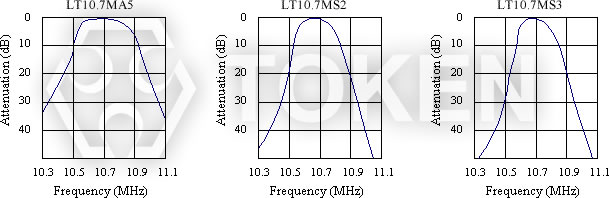
Technical Characteristics (LT10.7M) For FM Receiver (Murata SFE10M7 FM-IF Compatible)
|
| Part Number |
3dB Band Width (kHz) |
20dB Band Width (kHz) max |
Insertion Loss (dB) max |
Spurious Attenuation (9-12MHz)(dB)min |
| LT10.7MA5 |
280±50 |
650 |
6 |
30 |
| LT10.7MS2 |
230±50 |
600 |
6 |
40 |
| LT10.7MS3 |
180±40 |
520 |
7 |
40 |
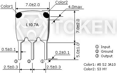
Input/Ouput Impedance: 330Ω
|
Technical Characteristics (LT10.7M A10) Low Insertion Loss (Murata SFE10M7 A10 Compatible)
|
| Part Number |
3dB Band Width (kHz) |
20dB Band Width (kHz) max |
Insertion Loss (dB) |
Spurious Attenuation (9-12MHz)(dB)min |
| LT10.7MA5A10 |
280±50 |
590 |
2.5±2.0 |
30 |
| LT10.7MS2A10 |
230±50 |
520 |
3.0±2.0 |
35 |
| LT10.7MS3A10 |
180±40 |
470 |
3.5±1.5 |
35 |
| LT10.7MJA10 |
150±40 |
360 |
4.5±2.0 |
35 |
Input/Ouput Impedance: 330Ω
|
Technical Characteristics (LT10.7M) Wide/Narrow Band-width (Murata SFE10M7 DBS Receiver Compatible)
|
| Part Number |
3dB Band Width (kHz) |
20dB Band Width (kHz) max |
Insertion Loss (dB) |
Spurious Attenuation (9-12MHz)(dB)min |
| LT10.7MA19 |
350min |
950 |
3.0±2.0 |
20 |
| LT10.7MA20 |
330±50 |
680 |
4.0±2.0 |
30 |
| LT10.7MHY |
110±30 |
350 |
7.0±2.0 |
30 |
| LT10.7MFP |
20min |
95 |
6.0max |
24(10.7±1.0MHz) |
Input/Ouput Impedance: 470Ω(MA19), 330Ω(MA20,MHY), 600Ω(MFP)