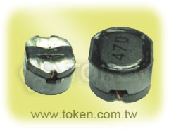
EMI High-Saturation Power Inductors (TPSRB) Shielded

The TPSRB series of wire wound, surface-mount inductor from DeMint Electronics is designed for general purpose inductor to eliminate EMI in power lines for telecommunications, test & measurement equipment, networking, portable electronic equipment, PCs, appliances, and other electronic devices.

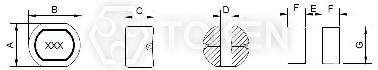
Developed to increase DC to DC converter efficiency through low DC resistance, the compact inductors save valuable board space, measuring only 5.6 mm x 6.2 mm x 3.2 mm for TPSRB63, 7.0 mm x 7.8 mm x 4.5 mm for TPSRB74, 9.0 mm x 10.0 mm x 5.5 mm for TPSRB105.

The inductors are magnetically shielded to prevent interference and operate in a wide temperature range. DeMint Electronics offers a variety of coils and inductors, including choke coils with low DC resistance for power supply circuits. Customers can select the optimum characteristics by choosing from monolithic or wire wound construction and a wide range of inductance values and tolerances with some types offering magnetic shielding.

Custom parts are available on request. DeMint will also produce devices outside these specifications to meet specific customer requirements, please contact our sales for more information.

Download Complete Datasheet EMI High-Saturation Power Inductors (TPSRB) PDF.

Features :
  1. Compact size.
  2. Magnetically shielded.
  3. Superior high Saturation for surface mounting.
Applications :
  1. Power supply for VCRS, OA equipment Digital camera, LCD television set, notebook PC, portable communication Equipments, DC/DC converters, etc.
Dimensions & Configurations (TPSRB) (Unit: mm)
Surface Mount (TPSRB) Dimensions
Surface Mount (TPSRB) Dimensions (Unit: mm)
Part NO A±0.5 B±0.5 C±0.5 D (Ref) E (Ref) F (Ref) G (Ref)
TPSRB63 5.6 6.2 3.2 1.8 1.7 2.25 5.5
TPSRB74 7.0 7.8 4.5 2.0 2.0 4.0 7.5
TPSRB105 9.0 10.0 5.5 2.8 2.5 5.0 9.5
Note: Design as Customer's Requested Specifications.
Electrical Characteristics (TPSRB)
Inductance (µH) TPSRB63 TPSRB74 TPSRB105
Marking L (µH) DCR (Ω) Max. IDC (A) DCR (Ω) Max. IDC (A) DCR (Ω) Max. IDC (A)
100 10 0.082 1.62 0.04 1.65 0.03 2.06
120 12 0.103 1.48 0.04 1.57 0.03 1.94
150 15 0.12 1.32 0.06 1.39 0.04 1.72
180 18 0.16 1.21 0.06 1.29 0.05 1.58
220 22 0.176 1.09 0.07 1.12 0.05 1.42
270 27 0.32 1.99 0.10 1.06 0.07 1.32
330 33 0.36 0.89 0.13 0.97 0.08 1.16
390 39 0.46 0.82 0.16 0.91 0.09 1.10
470 47 0.5 0.75 0.19 0.80 0.11 1.00
560 56 0.67 0.68 0.21 0.76 0.11 0.93
680 68 0.74 0.62 0.24 0.68 0.14 0.85
820 82 0.82 0.57 0.32 0.62 0.17 0.79
101 100 1.15 0.51 0.36 0.55 0.22 0.72
121 120 1.26 0.47 0.39 0.49 0.27 0.63
151 150 1.41 0.42 0.49 0.44 0.35 0.55
181 180 2.28 0.38 0.61 0.4 0.42 0.5
221 220 2.54 0.35 0.72 0.36 0.48 0.47
271 270 3.0 0.31 0.83 0.33 0.58 0.41
331 330 5.4 0.28 0.74 0.37
391 390 6.26 0.26 0.82 0.35
471 470 6.5 0.24 0.96 0.33
Note:
  • Measuring Frequency. L: <100uH 以上(100KHz/0.25v) L:>100uH 以上(1KHz/0.25v).
  • IDC:The current when the inductance becomes 35% lower than its nominal value. and temperature rise 40°C Δt=40°C (ta=20°C).
Order Codes (TPSRB)
TPSRB63 - 100 M
 
Part Number
TPSRB63
TPSRB74
TPSRB105
 
Inductance
100 10.00µH
101 100.00µH
Tolerance
J ± 5%
K ± 10%
L ± 15%
M ± 20%
P ± 25%
N ± 30%