4-Terminal Connection Kelvin Current Sensing Chips (LRF)
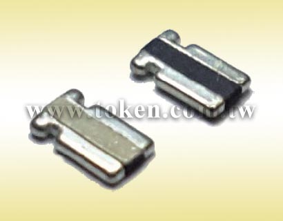
DeMint extends its surface-mount current sensing series with (LRF). This 4-terminal connection Kelvin chip resistor derivative in 1/2 watt and 1 watt package sizes. TCR down to 150ppm and enables tight tolerances down to 1% for increased measurement accuracy. DeMint LRF0612 combines tight tolerance and low TCR with extremely low resistance values down to 0.5mΩ in the compact 0612 case size.
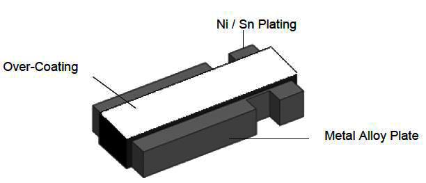
Employing the same Ni-Cu or Mn-Cu resistive element this product affords the user an added advantage of a built in 4-terminal design with 2 larger electrodes for current management and 2 smaller electrodes for voltage measurement. This results in a pulse tolerant, tight tolerance resistor in the 0612 package size that maintains the superior electrical characteristics of the surface-mount construction.
With its 4-terminal construction, the device reduces system errors while eliminating the need for system calibration. Also, LRF's low resistance value minimises excess power dissipation while its tight tolerance and low TCR improve circuit accuracy by reducing measurement error or eliminating the need for calibration during manufacturing or in the field, which reduces costs and/or improves end product performance.
The LRF0612 is suitable for all types of voltage division, current sensing, and pulse applications in power management for cell phones; VRMs for laptops, DC/DC converters for servers, and Li-Ion battery management and safety; industrial instrumentation; and automotive electronic control such as audio, transmission, anti-lock brakes, engine, and climate controls.
Like all current sensing chip resistors, LRF0612 features an all-welded construction that contributes to its superior electrical performance. A proprietary processing technique produces extremely low resistance values ranging from 0.5mΩ to 5mΩ, with tight tolerances of 1%, 2% and 5%. The device is lead-free, RoHS-compliant, and DeMint Green. For non-standard technical requirements and special applications, contact us with your specific needs.
Downloads Complete Specification PDF 4-Terminal Connection Kelvin Current Sensing Chips (LRF).
- 4-Terminal Kelvin design, Durable with all-welded construction.
- Solid metal strip nickel-chrome or manganese-copper alloy resistive element.
- Ideal for all types of current sensing, voltage division and pulse applications.
- Proprietary processing technique produces extremely low resistance values.
- Over Coating : molding Compound UL-94 grade.
- Automotive: Electronic controls (engine and transmission controls, audio electronics, climate controls, anti-lock brakes, etc.).
- Computer: Power management / safety, DC/DC converter, VRMs, Li-Ion battery management.
- Telecommunications: Power management in cell phones.
- Industrial: Instrumentation, inverter air conditioning.
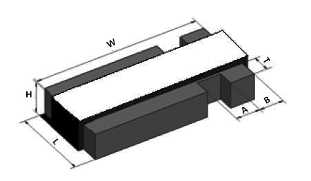
| Dimensions Unit: mm (LRF) | |||||||||
|
|||||||||
| Type | Power Rating at 70℃ (W) | Resistance Range (mΩ) | L±0.2 (mm) | W±0.25 (mm) | H±0.2 (mm) | T±0.25 (mm) | A±0.13 (mm) | B±0.13 (mm) | |
| LRF0612 | 1/2 | 0.5~5 | 1.65 | 3.05 | 0.65 | 0.4 | 0.51 | 0.51 | |
| LRF0612 | 1 | 0.5~5 | 1.65 | 3.05 | 0.65 | 0.4 | 0.51 | 0.51 | |
| Recommend Land Pattern (LRF) | ||||||||
|
||||||||
| Type | Maximum Power Rating (Watts: W) | Resistance Range (mΩ) | Dimensions (mm ± 0.1) | |||||
| A | B | C | L | F | ||||
| LRF0612 | 1/2W, 1W | 0.5 ~ 5 | 2.3 | 1.0 | 0.8 | 0.7 | 0.4 | |
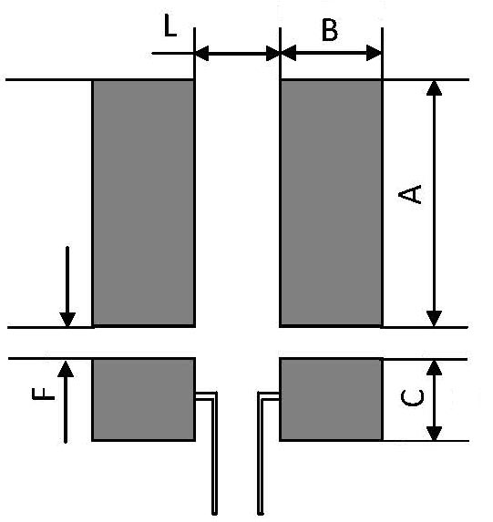
*Remark: Copper foil minimum thickness of PCB: 3oz
| Electrical Characteristics (LRF) | ||||||
| Type | Power Rating at 70°C | Maximum working voltage (V) | Resistance Range (mΩ) | TCR (ppm/°C) | Tolerance (%) | Operating Temperature Range |
| LRF0612 | 1/2W, 1W | (P x R)1/2 | 0.5mΩ ≤ R ≤ 3mΩ | ±200 | ±1%, ±2%, ±5% | -55℃~+170℃ |
| 3mΩ ≤ R ≤ 5mΩ | ±150 | |||||
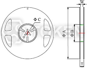
| Packing Quantity & Reel Specifications (LRF) | |||||||||
|
|||||||||
| Type | Packaging Quantity | Tape Width | Reel Diameter | ΦA (mm) | ΦB (mm) | ΦC (mm) | W (mm) | T (mm) | |
| LRF0612 | 4,000 pcs | 8 mm | 7 inch | 178.5±2.5 | 60.0±1.0 | 13.0±1.0 | 9.0±1.0 | 11.5±1 | |
| Emboss Plastic Tape Specifications (LRF) | ||||||||||||
|
||||||||||||
| Type | A (mm) | B (mm) | W (mm) | E (mm) | F (mm) | P0 (mm) | P1 (mm) | P2 (mm) | ΦD0 (mm) | ΦD1 (mm) | T (mm) | |
| LRF0612 | 3.50±0.10 | 6.70±0.10 | 12.0±0.30 | 1.75±0.10 | 5.5±0.05 | 4.0±0.10 | 4.0±0.10 | 2.0±0.05 | 1.50±0.10 | 1.50±0.25 | 1.2±0.15 | |
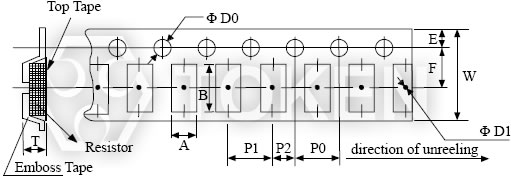
| Notice : |
1. The cumulative tolerance of 10 sprocket hole pitch is ±0.2mm. |
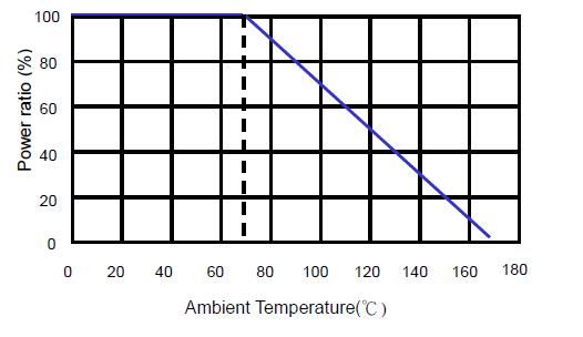
| Derating Curve | ||||||
|
||||||
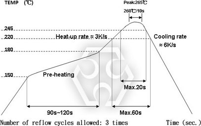
| Reflow Condition | ||||||
|
||||||
| Environmental Characteristics (LRF) | ||
| Item | Requirement | Test Method |
| Temperature Coefficient ofResistance (T.C.R.) |
As Spec.
|
IEC60115-1 4.8 JIS-C-5201-1 4.8 -55°C ~+125°C, 25°C is the reference temperature. |
| Short Time Overload |
±1%
|
IEC60115-1 4.13 JIS-C-5201-1 4.13 5*rated power for 5 seconds. |
| Insulation Resistance |
>100MΩ
|
IEC60115-1 4.6 JIS C 5201-1 4.6 100V DC for 1 minute |
| Endurance |
±2.0%
|
IEC60115-1 4.25 JIS-C-5201-1 4.25.1 70±2°C, RCWV for 1000 hrs with 1.5 hrs “ON” and 0.5 hrs “OFF” |
| Moisture no Load |
±1%
|
IEC60115-1 4.24.2.1a JIS-C-5201-1 4.24.2.1a 85°C, 85%RH, 1000 Hrs. |
| High Temperature Exposure |
±2.0%
|
IEC60115-1 4.23.2 JIS-C-5201-1 4.23.2 At +170°C for 1000 Hrs. |
| Low Temperature Storage |
±1%
|
EC60115-1 4.23.4 JIS C 5201-1 4.23.4 At-55°C for 1000 Hrs. |
| Bending Strength |
±1%
|
IEC-60115-1 4.33 JIS-C-5201-1 4.33 Bending width 2mm once for 5 seconds. |
| Solderability |
95% Min. coverage
|
IEC-60115-1 4.17 JIS-C-5201-1 4.17 245±5°C for 2±0.5 seconds. |
| Resistance to Soldering Heat |
±0.5%
|
IEC-60115-1 4.18 JIS-C-5201-1 4.18 260±5℃ for10±1 sec 2 cycles. |
| Thermal Shock |
±1%
|
IEC-60115-1 4.19 JIS-C-5201-1 4.19 -55°C ~ 150°C, 300 cycles, 15min per extreme condition. |
| Order Codes (LRC) | |||||||||||||||||||||||||||||||||||||||||||||||||||||
| LRF | 0612 | F | TR | F | T | 0m75 | M | ||||||||||||||||||||||||||||||||||||||||||||||
 |
|
|
|
|
|
|
|
||||||||||||||||||||||||||||||||||||||||||||||
|
|
|
|
|
|
|
|
||||||||||||||||||||||||||||||||||||||||||||||