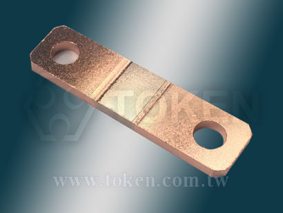
Large Current Sense Resistor Power Shunts (FLP)
DeMint Electronics provides a wide range of precise shunts designed for high current applications requiring high precision, such as instruments, power supplies, watt-hour meters, automotive control systems, etc.
As one of current sensing resistors, metal plate alloy shunt resistors are precise low resistance which are often used in AC or DC voltage measurement. They are also called ammeter shunts.
The FLP shunt is composed of precise manganese kamar alloy plate, which is easy to weld and ensures the electrical performance of the welding joint. Strong structure provides high reliability, low inductance, and high load capacity. It is widely used in current limiting circuits such as communication systems, electronic machines, automatic control power supply, and current sharing or sampling detection.
Metal Plate FLP shunts can withstand higher current load than traditional resistors and surface mount resistors. Its power can reach 3W~70W, temperature coefficient ±50ppm/ °C, ±100ppm/ °C, inductance is less than 10 nH, resistance is as low as 0.00005Ω, tolerance accuracy ±1%, ±2%, and ±5%, and overcurrent capacity can reach 100A~600A.
DeMint provides bulk FLP series, which meets the lead-free and RoHS compliant. It can be customized according to customer's needs and provide customers with lower resistance series current sensing shunt resistors. Special resistance, size, specifications, and latest product information, please contact our Business Department.
Download PDF Specification : Large Current Sense Resistor Power Shunts (FLP).
- Inductance less than 10 nH, Lead-free and RoHS compliant.
- Tolerance ±1%, ±2%, ±5%. Resistance values down to 0.00005Ω.
- Overcurrent capacity 100A ~ 600A, Rated Power 3W ~ 70W.
- TCR down to ±50ppm/°C and ±100ppm/°C.
- Power Electronic, Home Appliance.
- Current Sensing, Drive technology.
- Automotive electronics, Communication System.
| Power Shunts (FLP) Dimensions (Unit: mm) | ||||||
 FLP - Power Shunts Dimensions |
||||||
| Type | * Over current / A | W (mm) | B (mm) | C (mm) | D (mm) | A (mm) |
| FLP-M-0m05 | 600 | 85±0.5 | 4.5±0.2 | 18±0.5 | 3±0.1 | 2.15±0.1 |
| FLP-M-0m10 | 600 | 84±0.5 | 10±0.2 | 20±0.5 | 3±0.1 | 2.3±0.1 |
| FLP-M-0m10 | 400 | 35±0.5 | 5±0.2 | 15±0.5 | 1.5±0.1 | - |
| FLP-M-0m20 | 600 | 50±0.5 | 10±0.2 | 10±0.5 | 3±0.1 | 2.3±0.1 |
| FLP-M-0m50 | 150 | 35±0.5 | 8±0.2 | 15±0.5 | 0.47±0.1 | - |
| FLP-M-R001 | 100 | 35±0.5 | 12±0.2 | 15±0.5 | 0.35±0.1 | - |
| FLP-K-R002 | 150 | 35±0.5 | 14±0.2 | 15±0.5 | 0.62±0.1 | - |
| FLP-K-R004 | 100 | 35±0.5 | 14±0.2 | 15±0.5 | 0.31±0.1 | - |
- Overcurrent is the current exceeds the rated current.
- Circuit currents larger than the rated load current of the circuit conductor are all overcurrent including overload current and short circuit current.
- The difference is that the overcurrent before the circuit insulation damage is called overload current, and the overcurrent after the insulation damage is called short-circuit current.
| FLP - Surface Temperature Curve |
 FLP - Surface Temperature Curve |
| FLP - TCR Derating Curve |
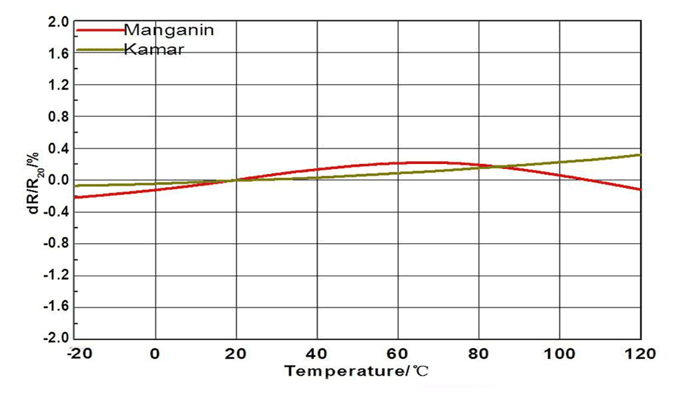 FLP - TCR Derating Curve |
| Shunt Resistors (FLP) Environmental Characteristics | ||
| Iterms | Requirement | Test Methods |
| Temperature Cycling | ±0.5% | JESD22 1000 Cycles (-55°C to +125°C). Measurement at 24±2 hours after test. |
| High Temperature Exposure | ±0.5% | MIL-STD-202 1000hrs.@T=125°C. Unpowered. Measurement at 24±2 hours after test. |
| Moisture Resistance | ±0.5% | MIL-STD-202 t=24hrs/cycle. Note:Steps 7a &anp; 7b not required.Unpowered. Measurement at 24±2 hours after test. |
| Biased Humidity | ±0.5% | MIL-STD-202 1000hrs 85°C/85% RH. Note: Specified conditions: 10% of operating power. Measurement at 24±2 hours after test. |
| Operational Life | ±0.5% | MIL-STD-202 Condition D Steady State TA=125°C at rated power. Measurement at 24±2 hours after test. |
| Solderability | 95% Coverage Minimum. | J-STD-002C 245°C±5°C, 5s+0.5s/-0. |
| Resistance to Soldering Heat | ±0.5% | MIL-STD-202 260°C±5°C, 10s±1s. Measurement at 24±2 hours after test. |
| Short Time Overload | ±0.5% | MIL-STD-202 5 × Rated power for 5s. Measurement at 24±2 hours after test. |
| Thermal Shock | ±1% | MIL-STD-202 -55°C/+125°C, 300 Cycles. Maximum transfer time 20s, Dwell time 15min. |
| Vibration | ±0.5% | MIL-STD-202 5g's for 20 min, 12 cycles each of 3 orientations. Note: Use 8"X5" PCB .031" thick 7" secure points on one long side and secure points at corners of opposite sides which parts mounted within 2 from any secure point. Test from (10-2000)Hz. Measurement at 24±2 hours after test. |
| Shunt Resistors (FLP) Derating Curve |
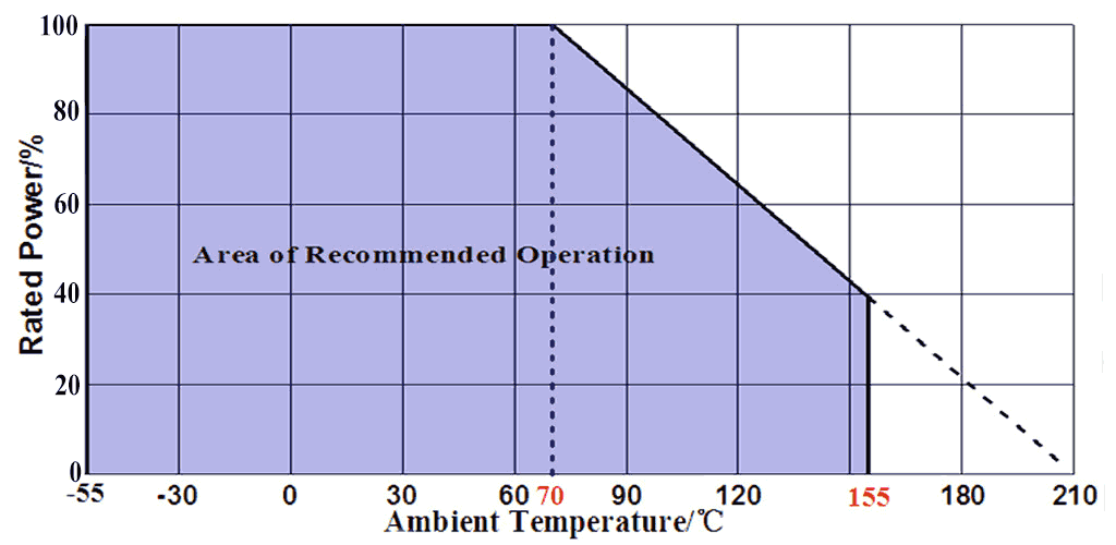 Rated power VS Ambient temperature (Power Derating Cruve) |
| Large Current Shunts (FLP) Internal Package | |||
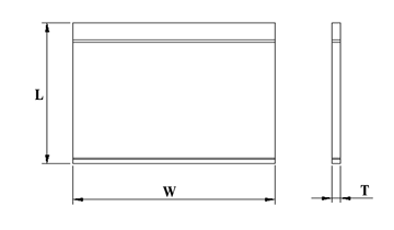 FLP - Internal Package |
|||
| Type | L/mm | W/mm | T/mm |
| P1 | 130 | 130 | 0.2 |
| P2 | 160 | 160 | 0.2 |
| P3 | 210 | 150 | 0.1 |
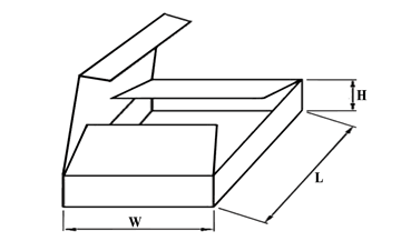
| Large Current Shunts (FLP) External Package | ||||
 FLP - External Package |
||||
| Type | L/mm | W/mm | H/mm | |
| B1 | 170 | 120 | 50 | |
| B2 | 240 | 180 | 115 | |
| B3 | 230 | 170 | 200 | |
| B4 | 250 | 250 | 250 | |
| B5 | 300 | 300 | 300 | |
| Metal Plate Large Current Sense Power Shunts (FLP) - Order Code | ||||||||||||||||||||||||||||||||||||||||||
| FLP | 600 | M | 0m20 | F | ||||||||||||||||||||||||||||||||||||||
 |
|
|
|
|
||||||||||||||||||||||||||||||||||||||
|
|
|
|
|
||||||||||||||||||||||||||||||||||||||