Characteristics And Properties of Filter Terminologies
What is "Ceramic Filter"?
A filter which uses a piezoelectric ceramics as an electrical-mechanical transducer and as a mechanical resonator. It provides simultaneously the electrical and the mechanical system within a single element.
Filter Characteristic Properties

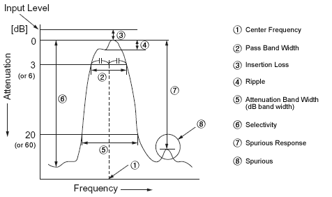
An example of filter Frequency characteristic
- Center Frequency (Symbol: f0; Unit: Hz):
It signifies the frequency in the center of the pass band width. However, the center frequency for some product is expressed at the point where the loss is minimum. - Pass Band Width (Symbol: PBW; Unit: Hz):
Signifies a difference between the two frequencies where the attenuation becomes 3dB from the level of the minimum loss point. - Insertion Loss (Symbol: IL; Unit: dB):
Expressed in the input and output level ratio at the point of minimum loss in dB. The insertion loss for some product is expressed in the input and output level ratio at the center frequency. - Ripple (Unit: dB):
If there are peaks and valleys in a pass band width, the ripple expressed the level difference of voltage between the maximum peak and minimum valley and it is expressed in dB. - Attenuation Band Width (Symbol: ABW; Unit: Hz):
Signifies a difference between the two frequencies where the attenuation becomes the specified values (dB) from the level of minimum loss.
(Example: Expressed at a point where the attenuation becomes 20 dB in case of 10.7 MHz filter.) - Selectivity (Unit: dB):
Expressed as the attenuation of the detuning point from the center frequency.
(Example: The attenuation that ±9 kHz was detuned from the center frequency in case of 455 kHz filter.) - Spurious Response (Symbol: sp; Unit: dB):
Expressed as the difference of voltage ratio between minimum attenuation point in the stop band range and minimum loss point in the pass band width by using dB (The stopped range is specified with each filter). - Spurious:
Signifies the frequency response based on the parasitic (unwanted) vibration against the frequency except the fundamental vibration. - Bottom Level (Unit: dB):
Signifies the minimum or average attenuation without both main response and spurious within the specified frequency range. - Input/Output Impedance (Unit: Ω):
Signifies the internal impedance value of the input and output side at the center frequency of ceramic piezoelectricity, and it is expressed in Ω. It causes no problem even if the input and the output are used in reverse with ceramic piezoelectricity, since the input and the output impedance are in a symmetry of substantially almost same value. - Impedance Matching: When connecting one electric circuit to another, or a component to another, or one electric circuit to a component, the electric energy is supplied most efficiently from the signal source to the load if the signal source impedance and the load impedance are same.
If these impedances are mismatched, electric energy escapes in form of a reflection. To match the signal source impedance and the load impedance is called the impedance matching. This is very important for ceramic piezoelectricity, as an improper impedance matching may cause various troubles.
General Information of Ceramic Filters
For more than two decades, piezo technology has been instrumental in the proliferation of solid state electronics. A view of the future reveals that even greater expectations will be placed on piezoelectric material in the area of new applications and for more stringent performance criteria in modern products.
DeMint sophisticated ceramics technology has greatly increased selectivity and wide-band characteristics, and has stabilized the characteristics of ceramic filters. The series covers a wide range of attenuation and bandwidths to allow selection of the most optimum filter characteristics for each application.
DeMint filters are bandpass filters consisting of one or more ceramic resonators connected in a ladder network configuration. Passband characteristics are determined by the relative resonant and anti-resonant frequencies of the resonators. Both narrow and wide passband configurations are manufactured by adjusting the resonator frequency characteristics.
The IC (Integrated Circuit) has found wide use in the field of commercial equipment, such as automotive radios, stereo systems, 2-way communications, TV sets, etc. Thus, new miniature integrated filters, with high performance, are extremely desirable for use in IF circuits.
Furthermore, radio wave disturbance due to rapid progress of data transmitting rate and remarkable sophistication of communication network have become significant traffic conflicts. Accordingly, the demand for filters with high selectivity and wide pass band width has boosted.
The IC application of the active elements will continue its progress, and there will be a growing demand for highly selective, non-adjustable, miniature and wide pass band width IF circuit.
Advantage of DeMint Electronics' Piezoelectric Filters
DeMint Electronics had been able to develop specialized piezo materials which when combined with an advance design have resulted in a complete line of practical, inexpensive piezo devices for entertainment and communications applications.
DeMint reliably deliver high-quality components according to the each customer special needs with respect to performance, costs, and technology modifications.
For marketing discontinuations or sourcing activities concerning Piezoelectric Filter products, you are encouraged to contact our Sales Department so the request can be properly directed within DeMint.